DIY Wind Simulator with RPM gauge
Introduction
Starting from version 2.112, the platform manager support various DIY accessories including e.g. wind simulator. You can build DIY using boards like Arduino, STM32 Discovery or other electronics platform. You can choose between using standard 3 wires PC fans, 4 wires PC fans or high performance in-line blowers. Furthermore, you can use a preassembled motor driver shield dedicated for your board or build the whole circuit yourself. Everything depends on your skills and budget.
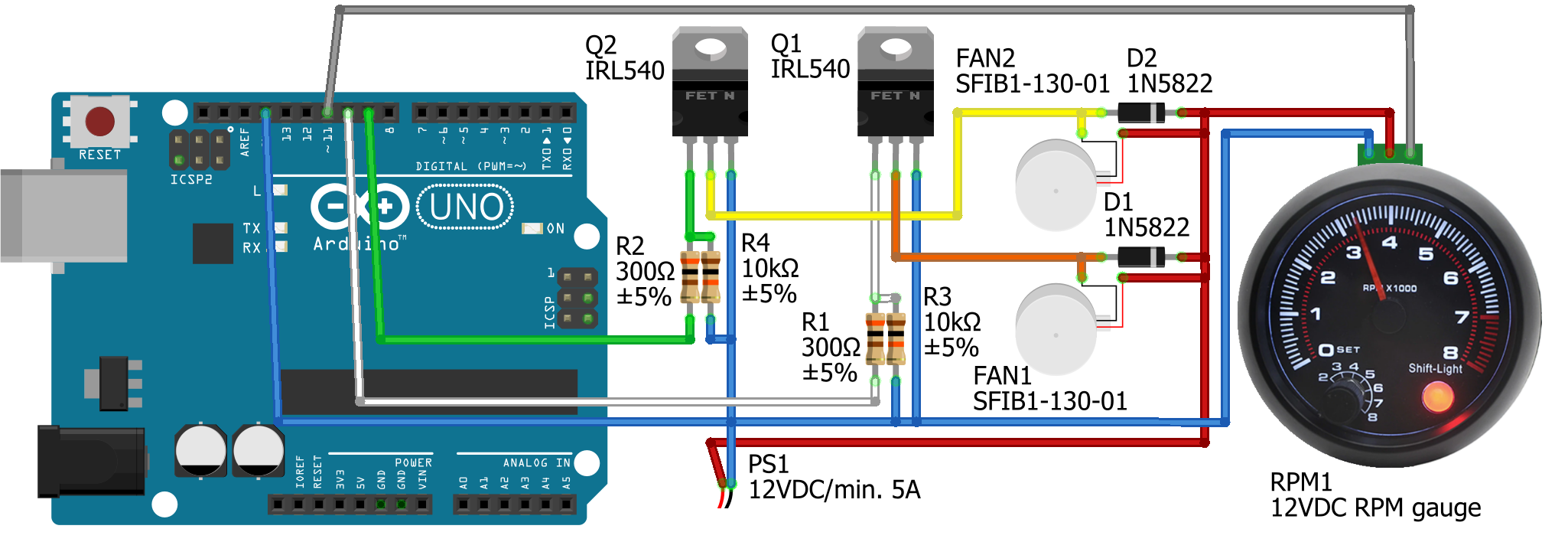
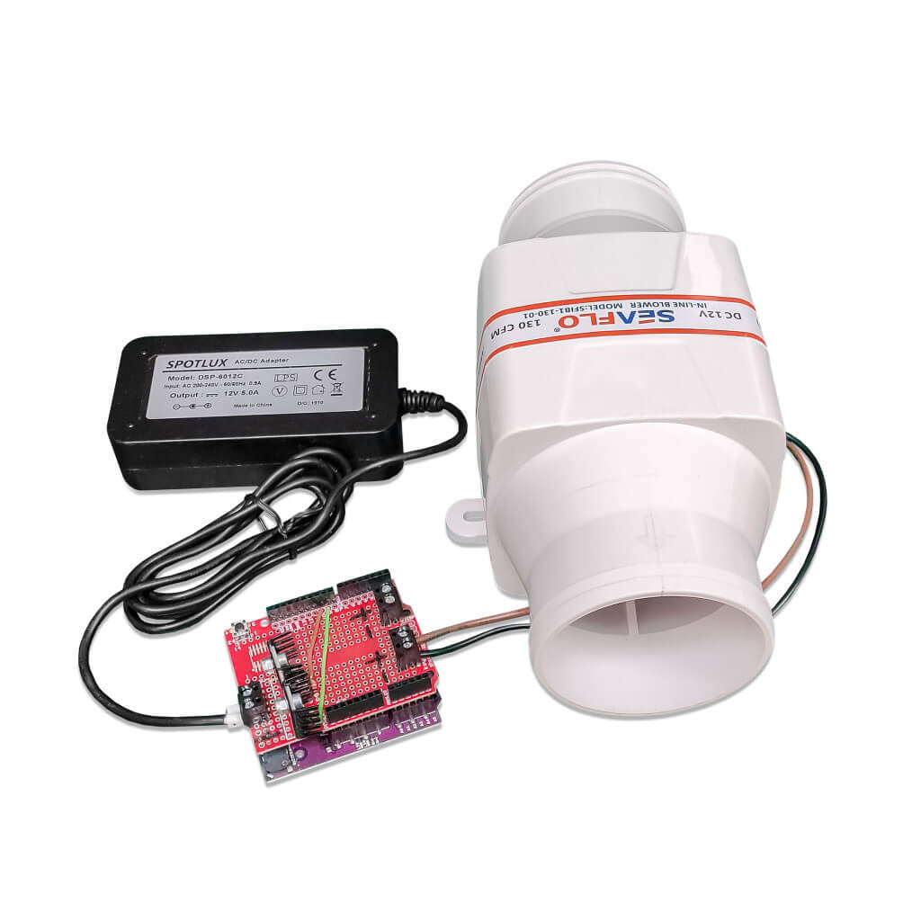
In this short article we have decided to go with Arudino Uno, in-line 12V blower and simple custom circuit to be assembled on the prototype shield.
Disclaimer
All DIY (do-it-yourself) projects are purely “at your own risk”. As with any DIY project, unfamiliarity with the tools and process can be dangerous. If you are at all uncomfortable or inexperienced working on these projects, especially but not limited to electronics and mechanical), please reconsider doing the job yourself. MotionSystems, its employees and partners will not be held responsible for any injury due to the misuse or misunderstanding of any DIY project.
Requirements
Before continue, make sure that you meet following requirements:
- you are familiar with Arduino programming (how to use ID, how to compile and flash the program, etc.)
- you have soldering equipment, and you know how to use it
- you understand that this is DIY project, “at-is”, without any warranty
- you agree to the above DISCLAIMER and TERMS & CONDITIONS
Design
The features of the following design are as follows:
- use of only simple THT components
- control up to two in-line blowers, 12VDC, max 5A per blower
- 14.5 kHz PWM to eliminate coil whine
- no overheating at low fan speed
- RS232 over USB for PC communication
- no overheating protection
ATTENTION: The circuit is not equipped with overheat protection. We haven’t had any overheating issues with this circuit, but you need to monitor transistors temperature when the blower is working at low speed.
Components
- 1x Arduino Uno or compatible board (e.g. Maker Uno)
- 1x proto shield, e.g. Iduino EX023
- 2x IRL540NPBF transistors
- 2x TO220 heatsink for transistors
- 2x THT resistor – 300R/0.1W
- 2x THT resistor – 10k/0.1W
- 2x Schottky diode – 1N5822
- 1x power supply – 12VDC, 5~10A
- 1x/2x in-line blower – 12VDC e.g. SFIB1-130-01
- some sockets and connectors
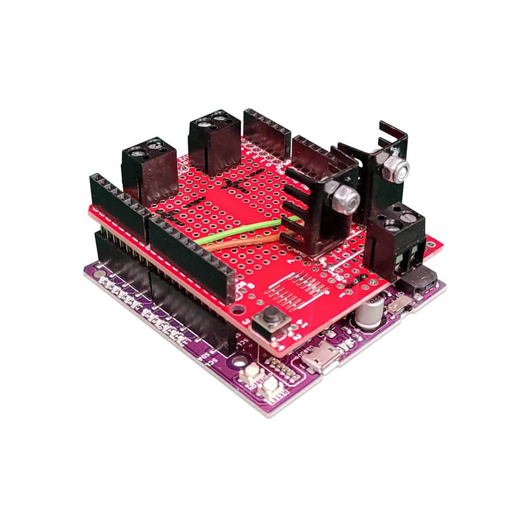
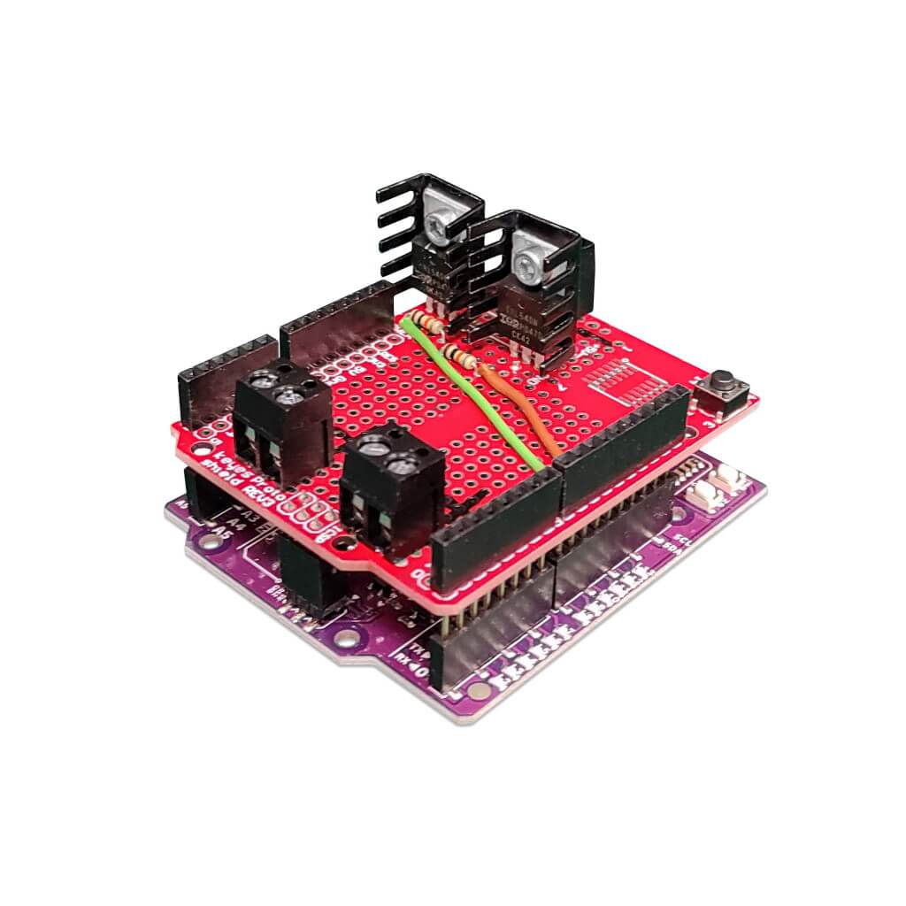
Assembly
Assembling everything together on proto-shield is pretty forward, no additional explanation is needed. The easier solution is to install transistors, resistors and sockets on TOP and Schottky diodes on the BOTTOM. Below are images showing how it can look after assembly for your reference.
Program
- The program turns off all fans if it does not receive a new command from the PC for 3 seconds. This is a protection against PC crash.
- The fans speed (PWM) is increased/decreased in small steps to avoid rapid current changes.
- The program supports two wind related commands: Lxx and Rxx. The first controls left fan, the second right fan. If you have only one fan, just connect is as left. xx is always a two-digit number, from 00 to 99.
- The program support one RPM related command: Exxxxx. xxxxxx is current vehicle engine RPM, and it is always a 5-digit number, from 00000 to 99999.
Source code
Use Arduino IDE or Visual Studio Code do compile the following code and flash it to your Arduino Uno board.
/*
 * Copyright (c) 2021 MotionSystems.eu
 *
 * Licensed under:
 * Creative Commons Attribution-NonCommercial-NoDerivs (CC-BY-NC-ND)
 * https://creativecommons.org/licenses/by-nc-nd/4.0/
 */

namespace AtmegaTimers
{
    static constexpr const struct Prescaler
    {
        uint8_t       clockSelectBits;
        unsigned int  divider;
        unsigned long limit;
    } TIM1_PRESCALERS[] = {     // ATmega328P PDF, page 110
        {                         _BV(CS10), 1,    65536ul * 1    }, // 0 0 1 | clk/1
        {             _BV(CS11)            , 8,    65536ul * 8    }, // 0 1 0 | clk/8
        {             _BV(CS11) | _BV(CS10), 64,   65536ul * 64   }, // 0 1 1 | clk/64
        { _BV(CS12)                        , 256,  65536ul * 256  }, // 1 0 0 | clk/256
        { _BV(CS12) |             _BV(CS10), 1024, 65536ul * 1024 }, // 1 0 1 | clk/1024
    }, TIM2_PRESCALERS[] = {    // ATmega328P PDF, page 131
        {                         _BV(CS20), 1,    256ul   * 1    }, // 0 0 1 | clkT2S/1
        {             _BV(CS21)            , 8,    256ul   * 8    }, // 0 1 0 | clkT2S/8
        {             _BV(CS21) | _BV(CS20), 32,   256ul   * 32   }, // 0 1 1 | clkT2S/32
        { _BV(CS22)                        , 64,   256ul   * 64   }, // 1 0 0 | clkT2S/64
        { _BV(CS22)             | _BV(CS20), 128,  256ul   * 128  }, // 1 0 1 | clkT2S/128
        { _BV(CS22) | _BV(CS21)            , 256,  256ul   * 256  }, // 1 1 0 | clkT2S/256
        { _BV(CS22) | _BV(CS21) | _BV(CS20), 1024, 256ul   * 1024 }, // 1 1 1 | clkT2S/1024
    };

    template <size_t N>
    void findPrescaler(const Prescaler (&prescalers)[N],
                       unsigned long reqTimerTicks,
                       uint8_t&  clockSelectBits,
                       uint16_t& period)
    {
        clockSelectBits = 0;
        period          = 0;

        for (const auto& prescaler : prescalers)
        {
            if (reqTimerTicks <= prescaler.limit)
            {
                clockSelectBits = prescaler.clockSelectBits;
                period = static_cast<uint16_t>(reqTimerTicks / prescaler.divider - 1);
                break;
            }
        }
    }
}

namespace PwmGeneratorTIM1
{
    static constexpr const int OUTPUT_PINS[] = { 9, 10 };

    static constexpr const unsigned int DUTY_MAX = 1023ul;

    void init(unsigned int freq_Hz)
    {
        auto timerTicks = static_cast<unsigned long>(clockCyclesPerMicrosecond() * 1000000ul / 2)
                          / (max(1u, freq_Hz));

        uint8_t  clockSelectBits = 0;
        uint16_t pwmPeriod = 0;
        findPrescaler(AtmegaTimers::TIM1_PRESCALERS, timerTicks, clockSelectBits, pwmPeriod);

        TCCR1A = 0; // clear control register

        pinMode(OUTPUT_PINS[0], OUTPUT);
        TCCR1A |= _BV(COM1A1); // Compare output mode

        pinMode(OUTPUT_PINS[1], OUTPUT);
        TCCR1A |= _BV(COM1B1); // Compare output mode

        ICR1   = pwmPeriod;
        TCCR1B = _BV(WGM13) | // PWM, phase and frequency correct
                 clockSelectBits;
    }

    inline void setPwmDuty(int pin, unsigned int duty)
    {
        unsigned long tmp = ICR1; // get maximum period
        tmp *= min(duty, DUTY_MAX);
        tmp >>= 10; // 0 to 1023
        static_assert(DUTY_MAX == 1023ul, "");

        switch (pin)
        {
            case OUTPUT_PINS[0]: OCR1A = tmp; break;
            case OUTPUT_PINS[1]: OCR1B = tmp; break;
            default:                          break;
        }
    }
}

namespace FreqGeneratorTIM2
{
    static constexpr const int OUTPUT_PIN = 11;

    inline constexpr unsigned long periodToTick(unsigned long period_us)
    {
        return period_us * clockCyclesPerMicrosecond() / 2;
    }

    void init()
    {
        pinMode(OUTPUT_PIN, OUTPUT);
    }

    void setPeriodInTicks(unsigned long timerTicks)
    {
        if (timerTicks == 0)
        {
            TCCR2A &= ~_BV(COM2A0); // Do not toggle OC2A on compare match
            return;
        }

        uint8_t  clockSelectBits = 0;
        uint16_t compareValue    = 0;
        findPrescaler(AtmegaTimers::TIM2_PRESCALERS, timerTicks, clockSelectBits, compareValue);

        OCR2A  = compareValue;     // OCR2A is PB3, mapped to Arduino Uno pin 11 (OUTPUT_PIN)
        TCCR2A = (_BV(WGM21) |     // 2 Clear Timer on Compare Match (CTC) Mode
                 ( _BV(COM2A0)));  // Toggle OC2A on compare match
        TCCR2B = clockSelectBits;
    }
}

namespace
{
    enum
    {
        BlowerLeft  = 0,
        BlowerRight = 1,

        BlowersCount = 2,

        BusyWaitTimeout       = 5,
        InactivityTimeout     = 3000,
        PwmDutyUpdateInterval = 20,

        SerialSpeed = 115200,

        PwmFrequency = 14500, // Incorrect value might overheat the transistor
        PwmDutyMin   = 100,   // Minimum PWM that makes any sense for blower
        PwmDutyMax   = 1023,  // It has to be <= PwmGeneratorTIM1::DUTY_MAX,
                              // put less than DUTY_MAX if the power supply turns off
        PwmDutyStep  = 40,

        RpmHzFor3000 = 200, // TODO: Change this value to match your RPM gauge!

        MaxSpeedFromPC             = 99,
        MaxBlowerSpeedDigitsFromPC = 2,
        MaxRpmDigitsFromPC         = 5
    };

    static_assert(static_cast<unsigned int>(PwmDutyMax) <= PwmGeneratorTIM1::DUTY_MAX, "");
    static_assert(RpmHzFor3000 >= 200, "Value less than 200 will cut anything below 1000 RPM");

    static struct
    {
        int current;
        int required;
    } g_pwmDuties[] = {
        { 0, 0 },
        { 0, 0 }
    };

    static unsigned long g_rpmReqTicks        = 0;
    static unsigned long g_dataReceivedMark   = 0;
    static unsigned long g_pwmDutyUpdateMark  = 0;

    bool isDataAvailable()
    {
        auto mark = millis();
        while (Serial.available() == 0)
        {
            if (millis() > mark + BusyWaitTimeout)
            {
                return false;
            }
        }
        return true;
    }

    bool readNumberFromSerial(long& value, int maxDigits)
    {
        value = 0;
        for (int i = 0; i < maxDigits; ++i)
        {
            if (! isDataAvailable())
            {
                return false;
            }

            auto tmp = Serial.read();
            if (! isDigit(tmp))
            {
                return false;
            }

            value *= 10;
            value += (tmp - '0');
        }
        return true;
    }
}

void setup()
{
    PwmGeneratorTIM1::init(PwmFrequency);
    PwmGeneratorTIM1::setPwmDuty(PwmGeneratorTIM1::OUTPUT_PINS[0], 0);
    PwmGeneratorTIM1::setPwmDuty(PwmGeneratorTIM1::OUTPUT_PINS[1], 0);

    FreqGeneratorTIM2::init();
    FreqGeneratorTIM2::setPeriodInTicks(0);

    Serial.begin(SerialSpeed);
}

void loop()
{
    auto ok   = readData();
    auto mark = millis();

    if (ok)
    {
        g_dataReceivedMark = mark;
    }
    else if (mark > g_dataReceivedMark + InactivityTimeout)
    {
        for (int i = 0; i < BlowersCount; ++i)
        {
            g_pwmDuties[i].required = 0;
        }

        g_rpmReqTicks = 0;
    }

    FreqGeneratorTIM2::setPeriodInTicks(g_rpmReqTicks);

    auto diff = mark - g_pwmDutyUpdateMark;
    if (diff < PwmDutyUpdateInterval)
    {
        return;
    }

    g_pwmDutyUpdateMark = mark;

    // To compensate not perfect intervals
    auto step = static_cast<int>(PwmDutyStep * diff / PwmDutyUpdateInterval);
    for (int i = 0; i < BlowersCount; ++i)
    {
        auto& info = g_pwmDuties[i];
        if (info.required == 0)
        {
            info.current = 0;
        }
        else if (info.required > info.current)
        {
            info.current = min(info.required, info.current + step);
        }
        else
        {
            info.current = max(info.required, info.current - step);
        }

        PwmGeneratorTIM1::setPwmDuty(PwmGeneratorTIM1::OUTPUT_PINS[i], info.current);
    }
}

bool readData()
{
    if (! isDataAvailable())
    {
        return false;
    }

    auto cmd = Serial.read();

    switch (cmd)
    {
        case 'L': return readDataBlower(BlowerLeft);
        case 'R': return readDataBlower(BlowerRight);
        case 'e': /*TODO: Shift light ON*/
        case 'E': return readDataRpm();
        default:  return false;
    }
}

bool readDataBlower(int blowerIndex)
{
    long speed = 0;

    if (readNumberFromSerial(speed, MaxBlowerSpeedDigitsFromPC))
    {
        g_pwmDuties[blowerIndex].required = 0 == speed
            ? 0
            : map(speed, 1, MaxSpeedFromPC, PwmDutyMin, PwmDutyMax);

        return true;
    }

    return false;
}

bool readDataRpm()
{
    long rpm = 0;

    if (readNumberFromSerial(rpm, MaxRpmDigitsFromPC))
    {
        static constexpr const auto FACTOR = 1000000ul * 3000/*rpm*/ / RpmHzFor3000;
        g_rpmReqTicks = FreqGeneratorTIM2::periodToTick(FACTOR / static_cast<unsigned long>(rpm));

        return true;
    }

    return false;
}
License
This file is licensed under the Creative Commons Attribution – NonCommercial – NoDerivatives 4.0 International – CC BY-NC-ND 4.0
Under the following terms:
You are free to:
- Share — copy and redistribute the material in any medium or format
The licensor cannot revoke these freedoms as long as you follow the license terms.
Under the following terms:
Attribution — You must give appropriate credit, provide a link to the license, and indicate if changes were made. You may do so in any reasonable manner, but not in any way that suggests the licensor endorses you or your use.
NonCommercial — You may not use the material for commercial purposes.
NoDerivatives — If you remix, transform, or build upon the material, you may not distribute the modified material.
No additional restrictions — You may not apply legal terms or technological measures that legally restrict others from doing anything the license permits.
First start – Arduino
- Do not connect the proto-shield yet to Arduino board yet
- Turn off ForceSeatPM
- Connect to PC
- Upload the firmware
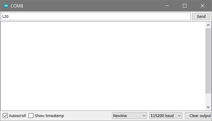
- From Arduino IDE start Serial Monitor (Tools/Serial Monitor)
- Set 115200 as baudrate
- Send L20 to the board
- If you have Maker Uno, the L9 led will illuminate for 2 seconds, and then it will turn off automatically.
First start – proto-shield
- Do not connect the proto-shield yet to Arduino board yet
- Connect in-line blowers to your proto-shield
- Connect power supply ATTENTION: the circuit does not contain reverse polarity protection!
- Turn on the main power.
- In-line blowers should NOT start
- Use multimeter to confirm 12VDC between + and – on the power supply socket.
- Use multimeter to confirm 12VDC between in-line blower #1 power and power supply’s GND.
- Use multimeter to confirm 12VDC between in-line blower #2 power and power supply’s GND.
Arduino + proto-shield
- Turn off the main power
- Attach proto-shield to Arduino
- Turn on the main power
- Connect Arduino to PC
- From Arduino IDE start Serial Monitor (Tools/Serial Monitor)
- Set 115200 as baudrate
- Send L20 to the board
- Left in-line blower should start working
- Send R30 to the board
- Right in-line blower should start working
- Check temperature of transistors ATTENTION! The circuit is not equipped with overheating protection!
ForceSeatPM configuration
- Start ForceSeatPM
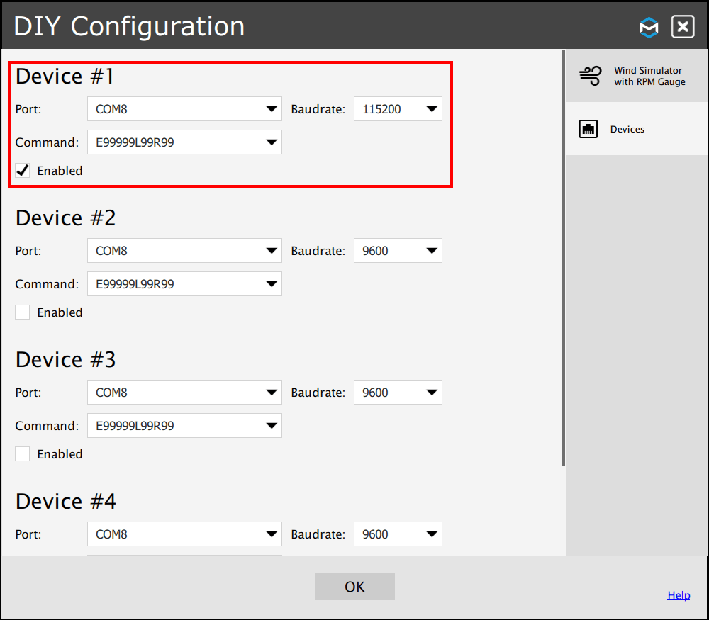
- Go to Tools and Diagnostic, DIY Configuration
- Setup serial port, baudrate (115200) and enable the system.
- Start your favorite game from the ForceSeatPM and enjoy the wind in your hairs.